Quick answer
Identify cubicle parts from the system outward: manufacturer, family, generation, panel or frame, junctions, bases, trim, worksurfaces, supports, storage, screens, raceways, and electrical or data components. Photograph labels and interfaces, map every part to a run, and obtain current manufacturer confirmation before reusing, substituting, loading, powering, or installing anything.
On this page9 sections
Key takeaways
- Identify the manufacturer, family, generation or revision, and original configuration before naming individual cubicle parts.
- Use labels, stamped numbers, documented dimensions, hole or slot patterns, profiles, connectors, and original drawing locations together; appearance alone is weak evidence.
- Separate structural parts, finish parts, work-support parts, storage, accessories, and powered or data components in the inventory.
- Do not substitute a similar-looking connector, support, fastener, trim piece, raceway, receptacle, or cable without written system-specific confirmation.
- Assign every reusable item to a run and condition on the current plan so shared junctions, ends, transitions, handed parts, and quantities reconcile.
- Keep electrical identification and handling under the responsible qualified parties; this guide is not an energized-work or wiring procedure.
Use a labeled parts atlas to structure the field record
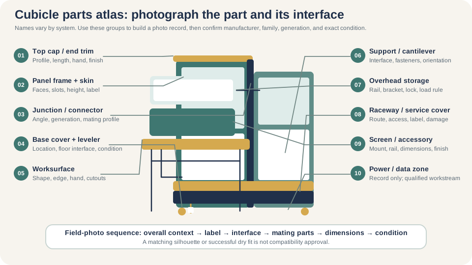
Identify the cubicle system before identifying the part
Office cubicles are product systems, not generic collections of panels and desks. A manufacturer may offer several families, and a family may change connectors, frames, skins, trim, supports, storage, dimensions, and electrical architecture over time. Begin with installed labels, purchase records, drawings, specifications, dealer records, and clear photographs of interfaces. When the label is missing, record the uncertainty rather than assigning a brand from color or silhouette.
| Evidence | Capture | Limit |
|---|---|---|
| Product label | Full label, manufacturer, series, model, date or code, certification marks, and location | A label may identify only one component, not the entire run |
| Original records | Purchase order, SIF or bill of materials, plan, elevation, quote, manual, and revision | The installed condition may have changed after purchase |
| Interface | Slot, channel, profile, hole pattern, connector, bracket, raceway, and mating surface | A close visual match is not a compatibility approval |
| Measured geometry | Overall and interface dimensions from named reference points with units and tolerance note | Nominal labels may differ from installed or connecting dimensions |
| Context | Run, junction, end, height change, surface support, storage, power, data, and adjacent parts | A loose part can be misidentified without its original relationship |
Current manufacturer literature shows why the system comes first. Steelcase's Answer specification guide organizes frames, junctions, skins, trim, worksurfaces, storage, screens, shared components, and powered choices as related conditions. Haworth's Compose product literature likewise presents multiple planning structures with selected panels, surfaces, storage, screens, glass, and power or data options. These are examples of documented kits, not evidence that their parts interchange. [1] [2]
Map panels, frames, junctions, bases, and trim
The vertical boundary may be a monolithic panel, a frame with removable skins or tiles, a spine, a beam, or another product structure. Record both faces, the top, bottom, ends, raceway locations, attachment points, and the parts that join one unit to the next. A corner, three-way junction, four-way junction, straight connection, height change, wall start, freestanding end, or door condition can require a different connector and trim package.
| Part group | Role | Identification fields |
|---|---|---|
| Panel, frame, spine, or beam | Creates the primary connected structure or service boundary | Type, width, height, thickness, face construction, raceway, slots, orientation, and label |
| Skin, tile, insert, or glass | Completes a frame face or functional finish zone | Position, face, segment height, material, attachment, edge, finish, and damage |
| Junction or connector | Creates straight, corner, multi-way, transition, wall-start, or end relationships | Angles, positions, post or bar type, fasteners, height, generation, and mating profile |
| Base, foot, glide, or leveler | Supports, stabilizes, or adjusts the lower condition | Location, adjustment range, floor interface, cover, fastener, and condition |
| Cap, trim, cover, or filler | Finishes top, end, base, seam, transition, opening, or service access | Exact run condition, length, profile, hand, finish, attachment, and cut status |
Identify worksurfaces, supports, storage, and accessories
A worksurface is defined by more than width and color. Capture shape, depth, thickness, edge, handedness, cutouts, height, finish, support method, and relationship to panels, frames, legs, pedestals, brackets, cantilevers, or rails. Do the same for overhead bins, shelves, towers, pedestals, lateral files, wardrobes, screens, doors, marker surfaces, monitor supports, and task accessories. Never treat storage as a substitute support unless the current system documentation shows that relationship.
| Group | Record | Operational check |
|---|---|---|
| Worksurface | Shape, dimensions, hand, edge, finish, cutouts, grommets, attachment points, and label | Chair, leg, knee, monitor, cable, adjacent surface, and user-adjustment envelope |
| Surface support | Bracket, cantilever, leg, rail, beam, panel connection, fasteners, and required orientation | Complete support set, documented loading, level, and correct interface |
| Below-surface storage | Pedestal or file type, mobility, hand, lock and key, top or support role, and clearances | Drawer opening, chair movement, cable path, cleaning, and egress from the station |
| Panel-hung storage | Bin, shelf, cabinet, rail, bracket, mounting elevation, panel relationship, and lock | Manufacturer stability and loading rules, door operation, head clearance, and removal sequence |
| Screen, door, or accessory | Material, dimensions, mount, compatible rail or surface, orientation, and finish | Sightline, swing or travel, route, cleaning, service, and future relocation |
Manufacturer loading and stability rules can depend on panel height, return panels, supports, the number and position of hung components, and other configuration details. The Answer guide, for example, publishes product-specific stability guidance for panel-hung components. Use the current instruction for the exact system and configuration; do not convert one published example into a universal shelf or storage rule. [1]
Keep power and data parts in a controlled workstream
Powered furniture can include raceways, covers, infeed components, harnesses, jumpers, power blocks, receptacles, pass-throughs, separators, grounding provisions, labels, and transitions. Data pathways, faceplates, jacks, cables, and telecommunications hardware may share the furniture without sharing electrical scope. Photograph identifiers and routing, but do not disconnect, modify, energize, splice, test, or substitute equipment based on this article.
| Record | Identification purpose | Responsible boundary |
|---|---|---|
| Equipment labels and markings | Tie each component to manufacturer, type, rating information, listing or labeling evidence, and original location | Qualified electrical review determines suitability, condition, connection, and reuse |
| Route and sequence | Show how components pass through frames, panels, junctions, covers, and transitions | Current system instructions and electrical design control permitted routing |
| Building interface | Identify source type, feed location, furniture entry, accessible covers, and trade handoff | Responsible electrical parties control source, capacity, protection, connection, testing, and inspection |
| Data pathway | Record pathway, separation, bend and service space, outlet location, label, and IT ownership | IT or telecommunications parties control design, cabling, termination, testing, and service |
| Condition and exceptions | Flag cuts, crushed parts, missing covers, heat, contamination, loose elements, mixed systems, and unknown modifications | Isolate and escalate; do not improvise repair or energization |
OSHA's general electrical requirements include installation and use in accordance with listing and labeling instructions where applicable, along with broader examination, installation, guarding, identification, and working-space provisions. The regulation does not tell a furniture inventory team that a found component is reusable. Retain the markings and route the decision to qualified parties using the current product and project documentation. [3]
Build an illustrated component and missing-parts record
-
Freeze the reference plan
Give rooms, runs, stations, junctions, ends, elevations, powered conditions, and loose-part zones stable identifiers on one current drawing.
-
Photograph before disturbance
Capture overall context, both faces, ends, top and base, labels, interfaces, supports, covers, damage, cables, and the part's relationship to adjacent components.
-
Assign a provisional identity
Record the evidence, confidence, measured features, possible family, and unresolved questions. Use unknown rather than forcing an unsupported identification.
-
Map the destination
Assign the part to a specific new run and condition, spare stock, vendor review, recycling, or hold area; do not mix accepted and uncertain inventory.
-
Reconcile assemblies
Check panels, junctions, ends, bases, trim, surfaces, supports, storage, screens, hardware, powered transitions, and handed items against every drawing condition.
-
Verify and release
Obtain manufacturer, dealer, installer, electrical, data, and design confirmation appropriate to the part, then issue a dated schedule with substitutions and holds.
| Field group | Columns |
|---|---|
| Identity | Item ID, proposed name, manufacturer, family, series, generation, model, date or code, label text, and confidence |
| Geometry | Width, height, depth, thickness, hand, orientation, profile, slot or hole pattern, interface, and units |
| Context | Original room, run, station, face, elevation, junction or end condition, adjacent parts, and photo IDs |
| Condition | Complete, damaged, cut, modified, contaminated, missing hardware, unknown power status, and disposition hold |
| Destination | New plan location, run condition, required mates, quantity needed, quantity accepted, spare, shortage, and substitute |
| Approval | Documents checked, reviewer, decision, date, limitations, responsible trade, and release revision |
Resolve compatibility and shortages before installation
Compatibility must cover geometry, connection, support, stability, load, finish, sequence, powered interfaces, and the exact planned condition. The same brand name is not enough, and a successful dry fit does not prove long-term suitability. Compare the current component schedule with the installation drawings, then place every uncertainty on a hold list with an owner and decision date. Buy or fabricate nothing from field dimensions alone when a documented system part is required.
Component-release gate
- Every run, junction, end, height change, wall start, door, surface, support, storage, screen, trim, and powered condition has a type and quantity
- Accepted reused parts have traceable identifiers, condition records, destination assignments, and current compatibility review
- New and reused finishes, profiles, generations, hands, cut conditions, keys, fasteners, and hardware are visibly distinguished
- Powered and data components remain segregated, labeled, protected, and controlled by responsible qualified parties
- Shortages, damaged items, substitutions, fabricated items, unavailable parts, and vendor decisions appear in one exception log
- Packing, transport, staging, floor distribution, hardware kits, protection, and loose-part containers use the same item and run IDs
- Current drawings, component schedule, quote, delivery list, installation plan, test plan, and acceptance checklist reconcile
- Only the authorized release revision can move to purchasing, delivery, assembly, energization, testing, or closeout
Frequently asked questions
What are the main parts of a cubicle?
Common groups include panels or frames, skins or tiles, junctions and connectors, bases and levelers, caps and trim, worksurfaces, supports, storage, screens, doors, accessories, hardware, raceways, and power or data components. The exact kit and names depend on the product system.
How do I identify an unknown cubicle part?
Photograph the label, overall context, interfaces, holes or slots, profiles, mating parts, dimensions, and original location. Compare purchase records and current manufacturer literature. Record uncertainty and obtain informed confirmation instead of naming it from color or appearance.
Are cubicle parts interchangeable between brands?
Do not assume so. Connection geometry, dimensions, supports, stability, loading, trim, generations, electrical architecture, and instructions can differ. Compatibility requires documentation for the exact parts and planned condition, even when items look similar or share a nominal size.
Can old cubicle electrical parts be reused?
That decision belongs to qualified responsible parties using markings, listing or labeling information, condition, system documentation, electrical design, applicable requirements, testing, and inspection. Do not energize, modify, mix, or substitute found components based on a visual inspection. [3]
Why count trim and hardware separately?
Ends, height changes, junctions, supports, access covers, and other conditions can require different caps, fillers, brackets, connectors, and fastener kits. A project can have enough main panels yet remain incomplete because these condition-specific items are missing.
What should be included in a cubicle parts inventory?
Include identity, geometry, original context, condition, photo IDs, system evidence, planned destination, mating parts, accepted quantity, shortage, disposition, review status, responsible trade, and release revision. Reconcile the inventory with the current plan rather than keeping an isolated warehouse count.
Sources and limitations
This guide supports identification and recordkeeping. It does not approve compatibility, structural loading, modification, electrical reuse, energization, installation, or project compliance.
Manufacturer documents support only their cited product structures and system-specific relationships; confirm the current revision, regional offering, exact parts, instructions, and planned configuration. The OSHA source must be applied by responsible qualified parties within its scope and does not turn an inventory observation into an electrical approval.
- Steelcase: Answer Solutions Specification Guide
- Haworth: Compose Workspaces Product Sheet
- Occupational Safety and Health Administration: 29 CFR 1910.303: General Electrical Requirements